
TOPO II Firmware
Content
HomeArticles
Gallery
Books
Lego
Personal
Links
Help
Articles
Original docAnnotated Topo
Specifications
Summary: "Growing up with Lucy"
TOPO II Firmware
JNI + JAR + Applet (+ Cygwin) HOWTO
Summary: "On Intelligence"
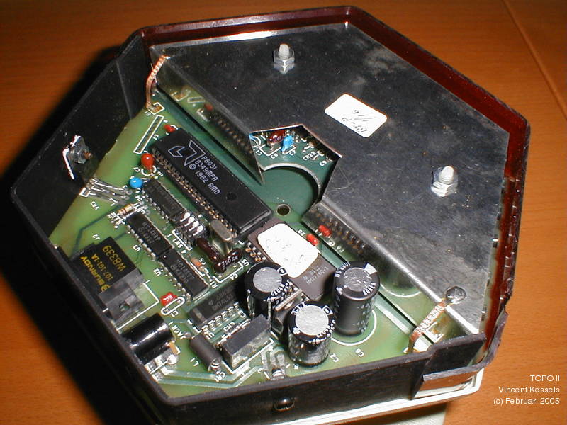
This article describes my attempts to reverse-engineer the firmware of the TOPO II robots. The purpose of this exercise is to be able to control the robot from my PC without using an Apple II and the original software (I don't have either). So my attempts are focused on finding the protocol and commands that the Base Communicator accepts from the host computer.
ROM
The robot uses 3 microcontrollers of the type 8031. This is a variant of the common 8051 microcontroller, but without internal EPROM.| Board | Base Communicator | |
| Label | D.L. V-1.00 5-DEC | |
| EPROM | HN462716g, Hitachi | |
| Size | 2k byte | |
| Intel Hex File | base-communicator.hex | |
| (Dis)Assembly | base-communicator.asm | |
| Control File1 | base-communicator.ctl | |
| Board | Communications Board | |
| Label | COM V-1.00 5-DEC | |
| EPROM | AM2764-4DC, AMD | |
| Size | 8k byte | |
| Intel Hex File | communications-board.hex | |
| (Dis)Assembly | - | |
| Control File1 | - | |
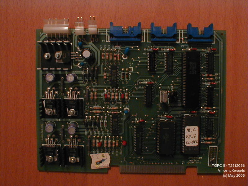
| Board | Motor Control Board | |
| Label | M.C. V0.16 12-DEC | |
| EPROM | AM2764-4DC, AMD | |
| Size | 8k byte | |
| Intel Hex File | motor-control-board.hex | |
| (Dis)Assembly | - | |
| Control File1 | - |
Tools & Documentation
I used the following tools to reverse-engineer the firmware.| Dataman S4 | Eprom Programmer & Emulator - Dataman S4 |
| D52 Disassembler | 8052/8035/8048/8041/Z80 Disassemblers for Linux/Windows |
| µCsim | Software simulator for MCS51, AVR core, Z80, HC08 and XA (Unix) |
I found the following documentation very usefull.
| Intel MCS51 Manual | MCS® 51 Microcontroller Family User's Manual from Intel |
| Intel MCS51 Documentation | MCS® 51/251 Microcontroller Documentation from Intel (Application Notes, Manuals, Product Briefs, Technical Notes and Datasheets). |
| 8052.com Tutorials | The 8052 Online Resource Tutorials |
| Standard 8051 Tutorial | The 8052.com Standard 8051 Tutorial |
Results so far
Here are the results I learned so far by studying the Base Communicator firmware.Serial Link
The serial link between the host computer and the Base Communicator is configured as 8 data bits, no parity bits and 1 stop bit (8,N,1). The switches on the Base Communicator define the baudrate as follow:| S1 | S2 | S3 | S4 | Baudrate |
|---|---|---|---|---|
| On | On | On | On | 9600 |
| Off | On | On | On | 4800 |
| On | Off | On | On | 2400 |
| Off | Off | On | On | 1200 |
| On | On | Off | On | 19k2 |
| x | x | x | Off | 9600 |
Communication Protocol
The communication protocol between the host computer and the microcontroller uses ASCII characters. The following characters are allowed:Bytes are send as two hexadecimal digits, where each character is one of:
'8', '9', 'A', 'B', 'C', 'D', 'E', 'F'
It seems that commands from the host are acknowledged with the character 'U'. This is also the first character that is send to the host when the microcontroller is reset.
Commands
Get Status command - 'Q'
If the character 'Q' is received the microcontroller replies with 1 status byte (not 2 characters!) and clears bit 0 of the status byte (if set). This command can be send at any time without impact on any partially send command.
| bit | Meaning |
|---|---|
| 7 | unknown |
| 6 | unknown |
| 5 | unknown |
| 4 | unknown |
| 3 | unknown |
| 2 | unknown |
| 1 | unknown |
| 0 | Invalid character received |
Note: this command violates the communication protocol by returning one byte in stead of 2 hexadecimal characters.
Warm Reset command - 'X'
If the character 'X' is received the microcontroller pushes the value 0x00A8 is pushed on the stack replacing the origional return address. The subsequent IRET instruction jumps to address 0x00A8, i.e. the initialisation code at the start of the Main function.
This command can be send at any time.