HIT-SWITCH MODIFICATION
Content
HomeArticles
Gallery
Books
Lego
Personal
Links
Help
Articles
Original docAnnotated Topo
Specifications
Summary: "Growing up with Lucy"
TOPO II Firmware
JNI + JAR + Applet (+ Cygwin) HOWTO
Summary: "On Intelligence"
print layout
TO:       ALL ANDROBOT MARKETING REPRESENTATIVES

FROM:     ENGINEERING

DATE:     16 MARCH 1983

SUBJECT:  MODIFICATION TO BY-PASS TOPO'S "HIT-SWITCH"
          (AKA: BODY REMOVAL PROCEDURE)

Topo's Safety Shut-off Switch is causing some logistical problems.  It
seems that an automatic reaction is to pat Topo on the top of his head
and accidentally shut him off.

In most situations, quick shut-off is desirable and necessary. But, in
a Show or crowded store, it can happen every few minutes, and is quite
disconcerting. So, some of you have suggested that a way to by-pass
the switch would be useful. We won't incorporate such a by-pass into
production units, but you might find it valuable to modify your demos,
particularly if they'll be used in shows.

Enclosed are comprehensive instructions. We thank Steve Whalen for
writing them. We also appreciate Steve's wit.

Directions for Installing the "Hit Switch" Disable Switch

Please read the instructions thoroughly and look at the illustrations and
Topo before you start.  If you have any questions, call Steve Whalen at
(408) 262-8676, Ext. 267.
1. Getting Ready
A. Equipment supplied by Androbot:
1. Aico toggle switch with hardware
a. Toggle switch
b. 2 hex nuts
c. I notched flat washer
d. a lock wisher.
2. 2 - 1Od finishing nails.
3. 4 extra rivets with posts.
B. Tools you will need:
1. Phillips head screw driver
2. Wire cutters and strippers
3. Center punch
4. Pencil
5. Hand power drill
6. Soldering iron and solder
7. Pliers or 5/16" wrench
8. Imagination and patience.
C. Read directions all the way through.
1. Have a feel for what you are going to do before you start.
2. Place the robots' foam perch on your work bench and the robot on
top of that.
ll. Installing By-pass Switch
A. Removing shell:
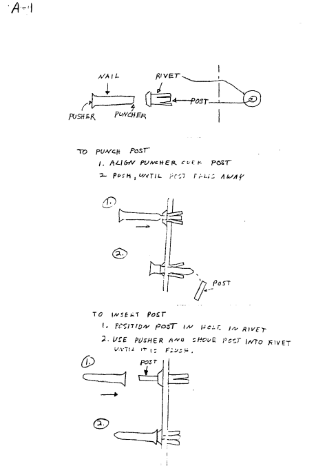
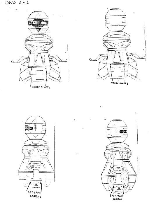
1. a. Using the pointed end of the IOd nail, punch the center
post (dwg. A-l) out of the 4 bellypan rivets. There are
2 in the front and 2 in the rear of the robot (dwg. A-2).
b. Remove rivets from body and place in a safe place. A small
box, jar, lid, etc., works.
2. Now, use your Phi I lips screw driver to remove the 4 leg/foot
screws and place them with the bellypan rivets. There are 2
screws on the left and 2 on the right leg/foot of the robot
(dwg. A-2).
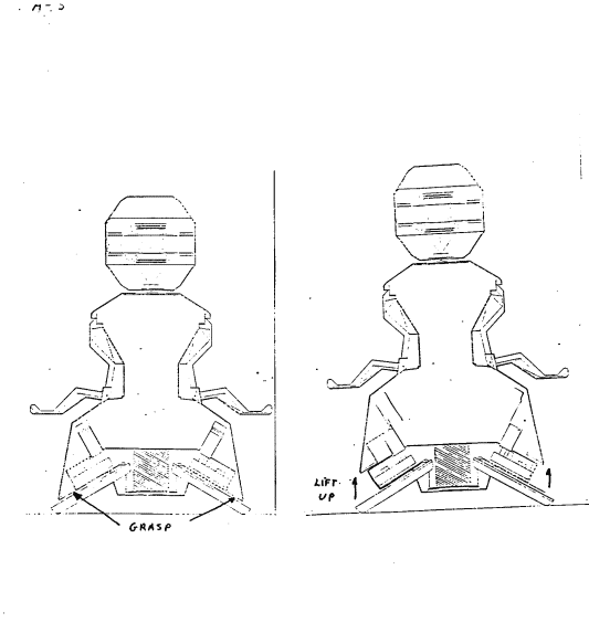
3. Position yourself behind robot, grasp the plastic shell under
foot lights and gently lift up until robot shell rests on base
(dwg. A-3).
-1-
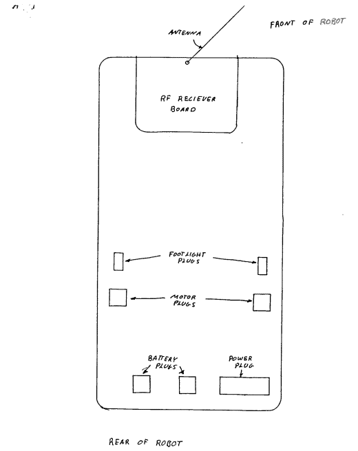
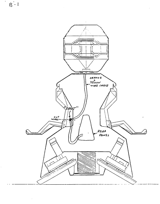
A.   4.   Reach inside and disconnect the power plug (dwg. A-4) from the
          motor control board.  Lift the shell up a little further and
          disconnect the 2 red, yellow and green foot light harness cables
          from the board, as well (dwg. A-4).

     5.   The shell has now been disconnected from the base, so lift it
          away and place it face down on a towel or clean area on your
          bench so that you are looking into the body cavity.  If you have
          trouble lifting the body off, either your antenna is caught up
          in the head or you've unplugged the motors instead of the foot
          lights.  In either case, don't worry, just ease the shell free
          and make sure to reconnect all the plugs when you put your robot
          back together.

     6.   Search for and find the posts from the bellypan rivets.  Put these
          with the rest of your hardware.

B.   Positioning bypass switch:

     1.   Identify orange and yellow twisted pair of wires from rear panel
          to the hit switch in the head.  Be careful while handling this
          cable throughout this procedure.  If you happen to yank on this
          cord too hard, you will pull the connector off the hit switch
          and you will have to open the head to reconnect it.

     2.   Locate a "spot" on the left inner arm where:

          a.   You would like the hit switch to be.

               1)   These directions tell you how to place it on the lower,
                    rear, side portion of the left inner arm -- but if you
                    want to put it somewhere else, don't feel obligated.

          b.   This "spot" must be in a position where the orange and yellow
               pair can reach easily so that there is some slack in the cable
               from both the head and the rear panel.

          c.   Mark this "spot" on the plastic shell with a pencil (dwg. B-l).

          d.   Now you are going to cut the orange and yellow cable (remem-
               bering Murphy's Law) so that after they are cut, both pairs
               of orange and yellow wires (from the head and from the rear
               panel)  will reach your "spot" easily and have some slack in
               their respective cables (dwg. B-l).

               1)   Murphy's Law of Wiring:

                    a)   Any wire cut to length will be too short.

               2)   Cut your wires.

                                 -2-
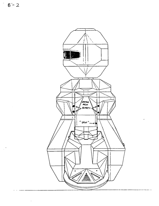
3. Drilling clearance hole for bypass switch:
a. Remove inner arm.
1) Punch posts on 4 inner arm rivets (dwg. B-2).
a) Find and save posts with other hardware.
b. Use center punch or nail to make a starter hole so your
drill bit doesn't wander off your "spot" as you make your
clearance hole.
c. Insert .2660 bit in your drill and make hole in your "spot".
d. Clean up you mess and put drill and bit away.
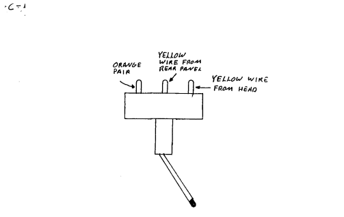
C. Soldering bypass switch to cable.
1. Strip the now 4 ends of your hit switch cable about 1/8".
2. Find some clever way of holding the toggle switch in a position
convenient for soldering the wires to it. We simply taped the
switch to the body, but if you have a vice or a better idea, use
it.
3. Solder both orange wires to one of the ends or outer posts of
the switch (dwgt. C-l).
4. Solder the yellow wire coming from the rear panel to the center
post of the switch (dwg. C-l).
5. Make sure you soldered the yellow wire coming from the rear panel
to the center post.
6. Solder your remaining wire, the yellow wire coming from the head,
to the remaining outer or end post (dwg. C-l).
7. Check your work. It's much easier to fix right now.
D. Attaching bypass switch to body.
1. Re-attach inner arm to body.
a. Line up inner arm holes on shell with those on the inner
arm itself.
b. Insert rivets through holes and use (dwg. A-l) the flat
end of your nail to push the posts in until they are flush
with the rivets -- be careful with the nail, don't puncture
yourself!
-3-
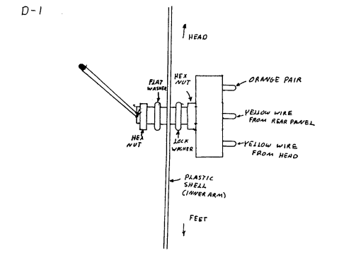
D. 2.    Attach bypass switch to arm.

         a. Place one of the hex nuts on the threads of the switch and
            spin it all the way down to bottom (dwg. D-l).

         b. Put lock washer over nut.

         c. Insert switch through the hole you drilled in the arm.

         d. Place flat washer on switch.

         e. Put on the remaining hex nut.

         f. Orient the switch so that the orange wires face the head
         (dwg. D-l).

         g. Use your 5/16 wrench to tighten the switch down.

         h. When your toggle switch is UP, the hig switch is IN CIRCUIT;
            when the toggle switch is DOWN, your hit switch will be
            DISABLED.

lll. Replace shell on base

A.   Follow the direction for removing shell, in reverse order.

     1.  Make sure:

         a. The antenna goes through the hole and into the head.

         b. All plugs are plugged into the receiver board on the base
            of Topo.

         c. The flaps of the torso go over the bellypan.

         d. The flaps of the legs go inside the bellypan.

IV. Test

A. Place switch in UP position.

   1.   Turn robot on.
   2.   Pat hit switch.

        a. Robot shuts off.

                                 -4-
B. Throw switch down.

   1.   Turn robot on.

        a. If your robot is on when you throw the switch, it will shut
           off.

   2.   Pat hit switch.

        a. Robot stays on.

                                 -5-