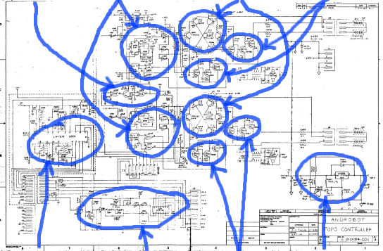
Annotated Topo
When I bought Topo I didn't receive any documentation on how he worked, nor the communication protocol was described. So the first thing I did was study the schematics. I will try here to explain what I did learn from the schematics. The schematics can be found in: Original Topo documentation.
There are three schematics available of Topo:
- Transmitter schematic
- Battery monitor schematic
- Controller schematic
Transmitter schematic
The transmitter consists of a discrete crystal oscillator. The crystal (X1) has a resonance frequency of 27.145 MHz. The signal is, via a buffer transistor (Q4), coupled to the antenna. There is no modulation of the signal generated by the oscillator.The signal is modulated by switching the whole oscillator on/off, aka AM modulation! A high level on the input line switches the oscillator on. A low level on the input line switches the oscillator off.
The 10K input resistor (R1) makes the input TTL and CMOS compatible. But a negative voltage reverse biases the BE-junction from the input transistor (Q1). Thus the input can not be a RS232 signal!
There can't be any statement made about the transmitted signal, apart from being an AM modulated signal.
Oscillator: X-tal
Frequency : 27.145 MHz
Modulation: AM
Protocol : Unknown
Input : TTL or CMOS
Battery monitor schematic
This schematic is not so interesting. The only thing worth mentioning is that, according to the schematic, the 'Hit switch' on top of Topo a normally closed switch is. When this switch is hit the power from the relay is cut. Thus cutting all current to the controller board and motors. Topo has to be manually reactivated.
Controller schematic
The schematic can be divided into a number of functionally different subsystems:
Receiver Decoder LED-driver (2x) 18V Power supply
Receiver
The receiver consists out of only one chip: LM1872. This chip (U201) is, according to the documentation of this chip (LM1872.pdf), capable of receiving and decoding the AM modulated signal from the transmitter. This chip can be used control two servo's as used by remote controlled airplanes and race-cars.This also explains how Topo is controlled and how the signal from the transmitter looks like (see box about servo signals).
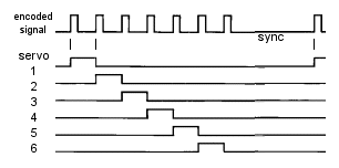
Servo signal'sThe signal which controls a servo is a TTL compatible pulse width coded signal (see image below). The pulse width varies between 1 ms and 2 ms. The pulse is repeated about every 20 ms. The information on position (or speed) of the servo is coded in the variance of the pulse width:
The signals of more then one servo signal can be combined to one, encoded signal (see image below). This encoded signal can be transmitted over a single RF band.  The encoded signal consists out of a series of pulses, each with a width of 0.5 ms. The distance from the start of a pulse to the start of the next is the width of the servo signal, i.e. from pulse 1 to pulse 2 is servo 1, from pulse 2 to pulse 3 is servo 2, etc. There is a sync pause of 3.5 ms between the last pulse and the first pulse of the next frame to depict the start of the next frame. A maximum of eight servo signal's can be combined to one encoded signal (8 x 2ms + 0.5 ms + 3.5ms = 20ms). |
Decoder
The decoder from the receiver chip is not used because it can only decode two (analog) servo signal's. The decoder is therefore separate implemented.The decoder consists out of three sections. The first section is a discrete buffer amplifier (Q301, Q302). (The signal from the receiver is not a logic signal!) The second section (U302) extracts the sync pulse from the signal. (The sync signal is logic '1' when the time between two pulses is larger then 2 ms. The third section (U301) is a shift register (ser in, parallel out). The sync pulse is fed to the serial in, which is clocked in with the pulses from the input signal. After the first pulse the sync pulse is '0'. Thus a single '1' is shifted from the first bit to the last, decoding the signal.
The first two decoded servo signal's are used to control the two motors of
Topo via the PWM-generators
PWM-generator
There are two PWM-generators: one for the left motor and one for the right motor. Both generators are identical. (I will use the upper generator for referencing parts in the next text.)The PWM-generator converts a servo signal to a Pulse Width Modulated signal (with a duty cycle of approx. 0 - 100%) and a direction signal (forward, reverse). To do this the PWM-generator 'subtracts' 1.5 ms from the servo signal and then stretches the pulse 40 times (from 0 - 0.5 ms to 0 to 20 ms).
The 1.5 ms reference signal is generated with monoflop U405, which is triggered with the positive flank of the servo signal. The subtraction is performed by EXORing (U402) the reference with the original signal, resulting in a pulsewidth of 0 - 0.5 ms. This pulse is stretched by charging capacitor C407 with a current 39 times bigger then the discharge current, creating the PWM signal.
The direction signal is obtained by using the 1.5 ms reference signal as clock for D-flipflop U406.
The direction and PWM signals are combined with NOR gates (U404) to create
two PWM signals from which only one at a time is active. These signals are
used to drive the H-bridges.
Dead-detector
The dead-detector around Q413 detects if there is a signal received. If there is no signal then both PWM-generators are stopped. This prevents Topo from taking of when he gets out of range.
H-Bridge
There are two H-Bridges: one for the left motor and one for the right motor. Both bridges are identical. (I will use the upper bridge for referencing parts in the next text.)The H-bridge is discrete build using 4 power transistors (Q403/Q404/Q405/Q406) and 2 signal transistors (Q401/Q402). The power transistors are bipolar ones, which have a total saturation voltage drop of 1 - 2 Volt. Thus the voltage over the motor is 1 - 2 volt lower then the voltage over the H-bridge (18V). There are also no flyback diodes. Probably because there is a transformer in the lines to the motor suppressing sudden power spikes.
The H-bridges are protected with 3 amperes fast blowing fuses. Thus the motors
have a maximum peak current of less then 3 ampere.
LED-driver
There are 4 LED-drivers: one for each PWM signal. The LED-drivers stretch the PWM signals to make them good visible. The LED's are used to give visual feedback over in which direction the motors/wheels are turning: Green -> forward, RED -> backwards.
18V Power supply
The 18V power supply is used to power the motors and the LED's. It's build using a LM338, which can deliver 5 ampere maximum. The power supply is slowly turned on using transistor Q600. Thus preventing large peak currents when the robot is turned on.
Conclusion
A number of conclusions can be made out of the schematics of Topo and the controller schematic in particular.- There is no feedback loop from Topo to the controlling computer. It's manually controlled by an operator.
- Topo uses 18V/54W motors (maximum, although stalk current could be more then 3 ampere).
- Using a microcontroller and a single-chip motor-driver would decrease the complexity significantly and increase the autonomity at the same time.